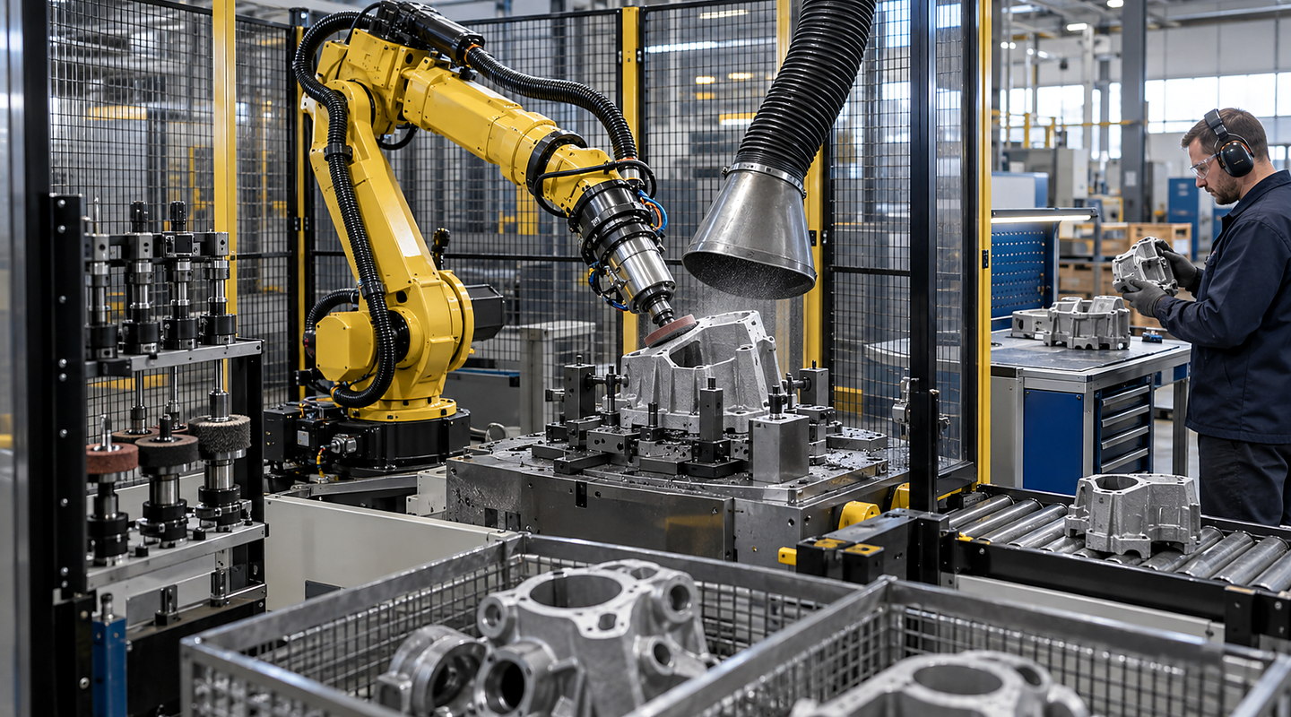
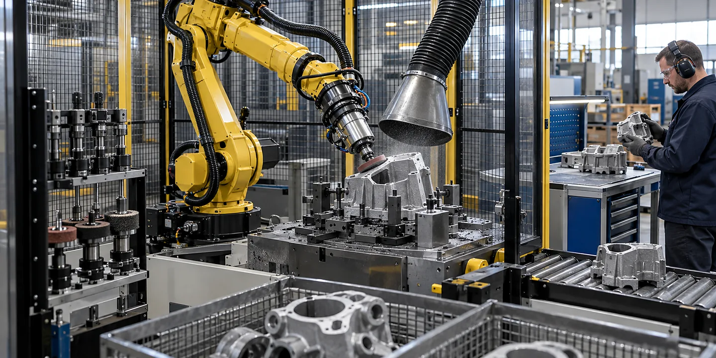
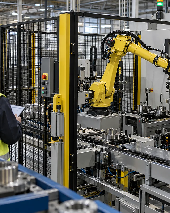
A robotic sprue-removal project must separate unwanted runner material while preserving the finished moulding. Define the permitted gate condition, incoming part presentation and the way the component is supported during separation before comparing tools or robot layouts.
Speak directly with Oxford Industrial Automation about robotic sprue removal and handling.
Quick answer
How can a robot remove and separate sprues from moulded components?
Provide moulded parts with their normal sprue and runner condition, plus the permitted finished edge or gate mark. Define how the part is located and supported during removal. Trial separation, inspection and waste handling, including incomplete cuts and dimensional variation, before agreeing the cell sequence.
Selection criteria
Prove the cut and the finished component
Use these decisions to define the proposed equipment and the checks needed for your application.
Decision 1
Record the moulding condition
Supply parts with normal runners and sprues from representative production. Include cavity variation and the condition at the point of removal. Note whether the trial uses freshly moulded or cooled parts so results are not compared under different conditions.
Decision 2
Define the gate finish
Mark the separation point and permitted remaining gate, surface damage or distortion using an approved reference. Include near-limit examples. The required finish determines the acceptance question; removing the runner is only one part of a successful operation.
Decision 3
Locate and support the part
Identify the datum, holding surfaces and support close to the separation point. Trial grip and fixture access without marking critical faces. Include normal moulding variation so the tool path is not based solely on one perfectly seated sample.
Decision 4
Select the separation method by trial
Compare suitable tool and motion concepts using the actual material and gate geometry. Check incomplete separation, fragments and damage to the retained part. Tool access and wear inspection need to be included in the proposed cycle.
Decision 5
Control runner and sprue waste
Show where separated material will fall or be placed and how it leaves the cell. Prevent waste from obstructing the next part or confusing a presence check. Include a full collection container and a retained sprue in the recovery assessment.
Decision 6
Confirm inspection and recovery
Define what proves separation complete before the part moves downstream. Agree handling of an ambiguous result, dropped part or interrupted cut. Retain the link between moulding variant, tool setup and the accepted finish.
Applications
Two useful starting points for robotic sprue removal
The right choice changes with part, product and process variation for robotic sprue removal & handling, arrival pattern and presentation, your line layout and required results.
Follow the sequence below to resolve the main specification questions before committing to equipment or installation.
01
Agree the finished-edge reference
Collect approved and rejected gate conditions with the moulding drawings and normal production samples.
02
Trial support and separation
Assess location, gripping, tool access and the retained component across relevant cavities and material conditions.
03
Integrate the waste route
Prove that parts and removed material leave through their intended paths without obstructing the next cycle.
04
Challenge exceptions
Include incomplete separation and interrupted operation in the acceptance scope, with a defined safe recovery and inspection route.
Practical decision guide
Compare degating trials across cavities and tool condition
The useful trial result is an accepted moulded component after separation, with the removed material accounted for. Keep cavity, material condition and tool setup visible in the comparison so a successful cut on one selected sample is not mistaken for a complete production result.
Preserve the sample origin
Identify the cavity or variant and the condition at the intended removal point. Keep the approved gate-finish reference with each group. If a concept is tried on cooled parts while production removal occurs earlier, record that difference and resolve it before drawing a conclusion about the production process.
Compare support and tool access together
Check where the part is restrained and where the separation force acts. Include the least accessible gate and the normal range of part location. Review marks and distortion after release as well as the remaining gate. Do not treat a fully detached runner as proof that the retained part is acceptable.
Observe the waste path through repeated cycles
Record incomplete cuts, retained fragments and waste entering the next fixture location. Include how the collection system is emptied and how a full or obstructed route is recognised. A clean single cut does not demonstrate that waste remains controlled over a longer sequence.
Plan the check after tool maintenance
Keep the approved tool position and sample references with the maintenance procedure. Agree which checks are repeated after replacement or adjustment, including the difficult cavity and boundary finish. Use the sprue-removal selection guide to compare tool life assumptions, access and acceptance responsibilities without inventing a guaranteed service interval.
Important limits
Know what needs a separate check
Cycle time depends on the complete process rather than robot speed alone.
Part presentation, tolerances and recovery cases must be included in feasibility work.
Collaborative operation or automatic handling cannot be assumed safe without an application assessment.
Your final solution for robotic sprue removal and handling must reflect the law, current standards and site-specific risks that apply to your installation.